
ALGO TEAM / HYDRAULICS GUIDE
How does Bosch Rexroth A10VO LA power control work?
Why does the pump deliver less oil as pressure rises? Why does 20 kW at 1500 rpm not mean 20 kW at every speed? Follow the detailed Rev B guide through the operating principle, manufacturer schematics and worked calculations.
1. What does LA control?
LA control changes the pump's swashplate angle and output flow to obtain approximately constant drive torque at varying working pressures. Within the control region, displacement and flow decrease as pressure rises. At fixed speed and approximately constant efficiencies, pressure multiplied by flow remains approximately constant.
LA is not a pressure-reducing valve or a relief valve continuously dumping the main flow. Instead of discharging excess oil to tank under a heavier load, it makes the pump produce less oil. DR pressure control serves a different purpose: it reduces displacement when the specified maximum pressure is reached. LA.D combines these two functions.
At low pressure, LA does not force the pump to consume its full rated setting. Before the torque limit is reached, the pump can operate at maximum displacement if another controller does not restrict it. Constant power describes the LA-controlled region under suitable conditions, not the entire operating range.
2. Swashplate, piston stroke and servo piston
A10VO Series 32 is an axial piston variable-displacement pump of swashplate design for open circuits. The prime mover rotates the shaft and rotary group. Swashplate angle determines the pistons' reciprocating stroke during a revolution; stroke determines the geometric volume displaced per revolution, Vg.
A larger angle increases piston stroke and Vg, producing more flow at the same speed. A smaller angle reduces stroke, displacement and flow. The shaft may still be turning near minimum stroke. Even then a real pump is not lossless: leakage, pilot consumption and mechanical losses remain.
The regulator changes the hydraulic force balance in the servo arrangement, moving the swashplate toward a smaller or larger displacement. This is a functional explanation. The source data sheet does not provide all internal spool, spring and servo dimensions. It cannot establish an undocumented internal part movement or an exact response time.
3. How does the LA loop respond to increasing load?
This sequence follows the guide's functional control explanation. It does not imply the presence of an electronic torque sensor or a software loop; it is a way to follow the result of the hydromechanical arrangement.
- A cylinder works against a heavier load, or a hydraulic motor sees greater resisting torque; the required working pressure rises.
- Pressure at pump outlet B is fed hydraulically back to the control arrangement.
- If Vg stayed unchanged, shaft torque would rise according to M = Vg × Δp / (20π × ηhm).
- When the pressure effect reaches the selected LA characteristic, the regulator directs the servo arrangement toward a smaller displacement.
- Swashplate angle decreases, piston stroke shortens and less volume is moved per revolution.
- At fixed speed, the decrease in Vg also reduces outlet flow.
- Higher pressure and smaller displacement establish a new balance; pump torque remains approximately at the LA setting.
- If load pressure falls again, greater displacement is permitted. A smaller displacement requested by DR or S control still takes precedence.
4. Flow, torque and power equations
Units are Vg in cm³/rev, n in rpm, Δp in bar, q in L/min, M in Nm and power in kW. ηv is volumetric efficiency and ηhm is hydromechanical efficiency. Δp is the pressure difference across the pump. The examples below neglect the inlet-side difference and treat it as approximately equal to pB.
The torque relation states M ∝ Vg × Δp. For approximately constant torque, doubling pressure requires roughly halving Vg. At fixed speed, flow is proportional to Vg too; therefore q × Δp appears approximately constant within the LA region.
Do not confuse shaft power with hydraulic output power. With the assumed efficiencies, 20 kW shaft power corresponds to approximately 17.48 kW hydraulic power: 20 × 0.95 × 0.92. This is a calculated result of the stated assumptions, not a measured performance value.
q = Vg × n × ηv / 1000
M = Vg × Δp / (20π × ηhm)
Pshaft = 2π × M × n / 60000
Phyd = q × Δp / 600
ηtotal = ηv × ηhm
5. What does 20 kW at 1500 rpm mean?
The data sheet asks customers to state the factory power characteristic together with its reference speed, using 20 kW at 1500 rpm as an example. This represents a torque characteristic of approximately 127.3 Nm.
The same torque setting gives approximately 13.3 kW at 1000 rpm, 20.0 kW at 1500 rpm and 26.7 kW at 2000 rpm. Power changes with pump speed; do not assume the controller maintains a 20 kW limit at all speeds. These values apply when the LA torque limit is reached, not to every lightly loaded operating point.
Mset = 20 × 60000 / (2π × 1500) = 127.3 Nm
6. Three operating regions and the p–Q map
The first region is maximum displacement: pressure is below LA control onset and Vg is approximately Vgmax unless another function limits it. The second is the LA torque/power limit, where Vg and q decrease as pressure rises. The third is D/DG pressure control: the pressure setting becomes limiting and the pump moves toward a smaller stroke.
On the manufacturer chart, the horizontal axis is qV as a percentage and the vertical axis is working pressure. The line at the full-flow side turns left after control onset: less flow is allowed at higher pressure. The lower torque chart and the ΔqV markings are reminders that real control can depart from an ideal mathematical curve.
280 bar is not an immutable physical limit for every LA pump. It is the standard DR setting in the referenced revision. This plot is educational. A valve closing or a lower flow request may place the operating point below the LA envelope.
7. NG71 worked example: 80–250 bar
Assume Vgmax = 71.1 cm³/rev, n = 1500 rpm, ηv = 0.95, ηhm = 0.92 and an LA setting of 20 kW at 1500 rpm. These efficiencies are teaching assumptions, not manufacturer efficiency maps. Calculated control onset is approximately 103.5 bar.
Values in the table are recalculated from the same equations and rounded to one decimal place. The DR transition band and actual leakage are not modelled in this example table. Without LA, a full-displacement pump at 250 bar would require approximately 307.5 Nm and 48.3 kW. LA reduces Vg to approximately 29.4 cm³/rev, keeping torque near 127.3 Nm.
ponset ≈ Mset × 20π × ηhm / Vgmax ≈ 103.5 bar
| Δp [bar] | Vg [cm³/rev] | q [L/min] | M [Nm] | Pshaft [kW] |
|---|---|---|---|---|
| 80 | 71.1 | 101.3 | 98.4 | 15.5 |
| 100 | 71.1 | 101.3 | 123.0 | 19.3 |
| 104 | 70.8 | 100.8 | 127.3 | 20.0 |
| 150 | 49.1 | 69.9 | 127.3 | 20.0 |
| 200 | 36.8 | 52.4 | 127.3 | 20.0 |
| 250 | 29.4 | 42.0 | 127.3 | 20.0 |
8. LA5–LA9 are not pressure cut-off settings
The table combines the control-onset pressure band with the torque range for each pump size. Moving from LA5 to LA9 means a higher onset/torque characteristic, not a change to the maximum DR pressure setting.
The NG71 example's 127.3 Nm lies in the 121.1–213.0 Nm range and is therefore consistent with LA7. The same kW and speed on a different pump size give a different control onset. Power alone is not enough to choose the code; pump size and reference speed also matter. The limits below preserve the source's notation.
| Code | Onset [bar] | NG45 [Nm] | NG71 [Nm] | NG100 [Nm] | NG140 [Nm] | NG180 [Nm] |
|---|---|---|---|---|---|---|
| LA5 | ≤ 50 | ≤ 42.0 | ≤ 67.0 | ≤ 94.0 | ≤ 132.0 | ≤ 167.0 |
| LA6 | 51–90 | 42.1–76.0 | 67.1–121.0 | 94.1–169.0 | 132.1–237.0 | 167.1–302.0 |
| LA7 | 91–160 | 76.1–134.0 | 121.1–213.0 | 169.1–299.0 | 237.1–418.0 | 302.1–540.0 |
| LA8 | 161–240 | 134.1–202.0 | 213.1–319.0 | 299.1–449.0 | 418.1–629.0 | 540.1–810.0 |
| LA9 | > 240 | > 202.1 | > 319.1 | > 449.1 | > 629.1 | > 810.1 |
Manufacturer reference: RE 92705, p. 13
9. Read the LA.D schematic from its ports
Do not confuse pilot lines with the main-flow line. The control arrangement changes the servo force balance. The diagram does not reveal spool dimensions, spring rates or exact movement times.
- B: main high-pressure outlet, where working pressure pB develops.
- S: pump inlet.
- L / L1: case-drain/tank connections; installation requirements must also be followed.
- MB: high-pressure measuring connection; the source specifies it for port plates 22 and 32.
- Servo arrangement: the adjustment mechanism that converts regulator action into displacement change.
- LA element: acts toward a smaller Vg according to the selected power/torque characteristic.
- DR element: requests a smaller Vg when the pressure setting is exceeded, limiting outlet pressure.
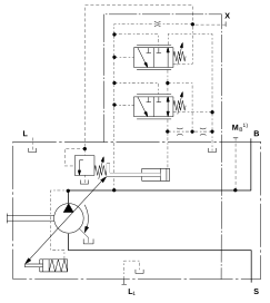
10. LA.D, LA.DG, LA.S and LA.DS
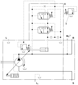
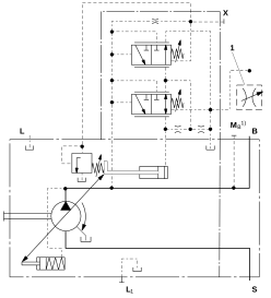
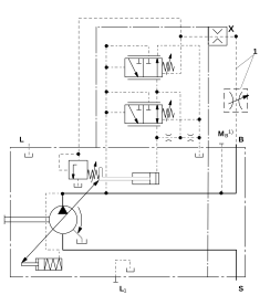
These schematics come from RE 92705 p.14. The external metering orifice, associated line and remote pressure valve are not automatically included in the pump delivery; the source's boundaries and notes matter.
| Variant | Power/torque | Pressure | Flow |
|---|---|---|---|
| LA.D | LA | Local DR | — |
| LA.DG | LA | Remote DRG / X | — |
| LA.S | LA | No D function | S with separate orifice |
| LA.DS | LA | DR | S with separate orifice |
11. LA.DG: what does the X line change?
The LA description refers to DR(G) for the pressure-control section. In DRG, an external pressure relief valve is connected to port X to establish the pressure reference remotely. Do not read this as a main relief valve dumping the pump's full delivery; it is part of the control connection.
The referenced revision specifies a standard DRG differential of 20 bar, an adjustment range of 10–22 bar, approximately 1.5 L/min pilot flow at X and a recommended maximum line length of 2 m. With X unloaded to tank, standby pressure can be approximately 1–2 bar above the adjusted differential, excluding system effects.
Consequently, do not assume that the remote valve setting and pressure at pump port B are identical numbers. The remote setting, control differential and line effects need to be considered together. These figures belong to the 2019 source revision and must be checked against the actual order code.
12. LA.S / LA.DS: orifice and pressure differential
Flow control uses the pressure difference before and after an adjustable metering orifice. The pump moves toward the displacement that maintains this differential near its setting, making orifice opening represent the consumer's flow request. The DRS arrangement referenced by the LA section specifies a standard differential of 14 bar and an adjustment range of 14–22 bar.
Flow control is possible below the LA power curve. If the orifice requests high flow but the LA limit allows less at the current pressure, the request cannot be fully met. In the laboratory's steady-state model, the actual LS margin can then decrease. That visualization is a model interpretation, not a manufacturer transient test.
13. Which regulator takes priority?
The manufacturer states that displacement reduction takes priority in controller combinations. The minimum relation below is a useful engineering interpretation, not a suggestion that hydraulic valves run a software min() function. The smallest permitted displacement limits the operating point.
S control may govern under a low load and low flow request. LA becomes limiting when load rises to the torque envelope. At the DR/DRG pressure limit, pressure control can request an even smaller Vg. A fully commanded joystick with low delivered flow is therefore not sufficient evidence of pump failure.
Vg,final ≈ min(Vg,LA; Vg,flow; Vg,pressure)
14. Interpreting behaviour in the field
These are behavioural interpretations from the guide, not definitive fault diagnoses. Do not change settings without evaluating the servo/pilot conditions and real machine measurements.
- Fast unloaded movement and slower loaded movement: the pump may have entered the LA region; compare pressure and flow.
- Pressure at the upper setting with very slow or stopped movement: check whether DR/DRG pressure limiting is active.
- Low pressure and low flow: S demand/orifice conditions or another restriction may be involved; do not attribute it to LA alone.
- Apparent power changes with speed: this can be expected from P = Mω with the same torque characteristic.
- Measurement set: actual pump speed, pB, flow, factory LA setting, DR/DRG setting, flow request and Vg/angle information when available.
15. Six short laboratory experiments
Start begins time recording; calculations remain visible in preview. Run experiment changes pressure. CSV export saves the recording. These experiments do not send commands to a physical machine.
- Start with NG71, 1500 rpm, a 20 kW reference setting and 80 bar: expect full displacement and approximately 101.3 L/min.
- Set pressure to 150, 200 and 250 bar: displacement/flow should decrease while torque stays near 127.3 Nm.
- In the LA region, change speed to 1000 and 2000 rpm: observe power and flow changing with the same torque setting.
- In D mode, reduce the DR limit from 280 to 220 bar: examine available flow as test load reaches the setting.
- Select S/DS and lower requested flow: observe the point moving below the LA envelope. In these modes load pressure and pump pressure are not the same input.
- At the same pressure, increase the reference power setting from 20 to 30 kW: permitted torque and displacement rise; compare the new control onset.
16. Model and application limits
The laboratory uses steady-state pump/orifice equations. Actual spool/servo transients, hysteresis, spring tolerances, oil compressibility, temperature/viscosity effects and detailed leakage maps are not solved. Zero indicated power at zero stroke does not mean that a real pump is lossless.
The data sheet gives a maximum LA pilot consumption of approximately 5.5 L/min. The DR setting range of 20–280 bar and standard setting of 280 bar are also controller data from the source revision. These details are reasons to use manufacturer verification rather than treating the assumed calculations as a complete pump specification.
This guide is for learning and preliminary assessment. Final pump selection, field adjustment and safety require the current manufacturer documentation for the appropriate order code and application-specific approval. The absence of D control in LA.S does not mean that a real circuit can be left without pressure protection.
Sources, revision and scope
Basis: ALGO TEAM A10VO LA Detailed Guide, Rev B. Manufacturer reference: Bosch Rexroth RE 92705/2019-03-25, particularly p. 7 and pp. 9–14. The link leads to a copy of the manufacturer's document hosted by Hydropart. The date identifies the source revision, not a claim that it is the current catalogue or that a product is currently available.
Bosch Rexroth — RE 92705/2019-03-25 (PDF)
Manufacturer information, assumed calculations and functional interpretations are distinguished. Schematics are copyright Bosch Rexroth AG. ALGO TEAM is an independent educational tool, not an official manufacturer training or selection application. This web publication does not modify the existing PDF guides.